)
)
)
)
)
)
)
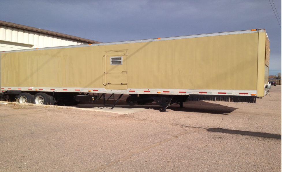
Frac Sand Water Treatment Facility
- Unit#
- H2O Treatment FCLTY
- Price:
- Call!
Detailed Specifications
| Truck Type | Miscellaneous |
Comments
BASIC INFORMATIONMU2 PRODUCT DESCRIPTION
Mobile Treatment Unit Version 2 (MU2) consists of two physical units, one being the control container which is a 45ft trailer mounted unit which houses the controls, pumps, dosing and press system associated with the second unit. The second unit being a frac tank modified which contains the tank and storage associated with the control unit. Within the customized frac tank there is an oil water separator, a DAF unit with integral cavitation/oxidation reactor, and oil storage.
The unit is designed for mobile deployment to oil and gas development sites for the treatment of water produced in the normal operations of such sites. The treatment regime is aimed at the treatment of the produced water for re-use in completion of the development of newly drilled wells also known as fracking.
The unit performance criteria are based on 250gpm of input waters, with oil/water separation capability of up to 5% content by volume. The unit is capable of treating up to 8,000 barrels of water per day and possesses the ability to treat both produced and flow-back waters, by varying chemical injection.
FLOW PATH
Inlet and outlet connections to feed and product tanks are located at the nose of the control trailer. Inlet water is pumped to the oil/water separator system. The oily water flows through coalescing packs and the free oil accumulates at the top of the chamber while water flows into a separate accumulation chamber. From this reservoir, water is pumped at high pressure into the oxidation/cavitation reactor. The free oil is pumped into an on board holding tank. On line analyzers determine Turbidity, pH, and conductivity of the water prior to entering the reactor. The reactor is integral to the DAF tank and the entrained air from the reactor lifts contaminants to the top of the DAF vessel. Chemicals are injected into the water pre, direct, and post reactor as necessary. Typical chemical dosing includes: metal based coagulant, polymeric flocculant, pH adjustment, reverse emulsion breaker, and oxidant. pH is monitored in the DAF vessel and the operational pH controls the injection of pH adjustment chemicals. After air entrainment the water/air/chemical solution is held in the DAF to allow time for the solids to bind together with the air and chemical modification to make them float as an aqueous sludge. The water without the solids travels under a weir plate and into the discharge tank, which is then pumped out to the desired storage tank external to the MTU. Prior to discharge, on line analyzers determine the conductivity and turbidity of the processed water. This continually verifies the performance of the unit and immediately indicates the need for any adjustment of the chemical dosing program which is easily accomplished.
The sludge is collected into a tank for pumping into the feed tank for the plate press by the operation of the Flights on the DAF. Typically a blanket of sludge is created and held in the DAF until it is approximately 4” deep, by this method little subsurface disturbance is created when the flights are operated. After the sludge is pumped to the press feed tank the sludge is built up in the feed tank to provide sufficient sludge to operate the press.
Press operation is commenced firstly closing the press and bringing the unit up to pressure. The sludge is then transferred by air driven pump until the pump reaches a set pressure which trips the pump off. The feed valves are closed and the sludge is held in the press for a period to dewater to the desired level. The water yielded from the sludge pressing is pumped back to the reactor feed tank.
COMPONENTS
Process pumps are Goulds SSH for low pressure and Goulds SSV for high pressure. Variable frequency drives are Allen-Bradley Powerflex 70. Pressure transmitters are Rosemount 3051. Level transmitters are Rosemount 3051, Wika submersible, and Flowline ultrasonic. Analytical instruments are Rosemount. Chemical injection pumps are Pulsatron. Control system is Allen-Bradley Contrologix. Internal low pressure piping is schedule 80 PVC. External low pressure piping is oil field hose with camlock couplers. High Pressure piping is 316L stainless steel.
FUNCTIONALITY
The units are completely transportable, as one is a semi-trailer and the other is a standard frac tank. All inter-connective hoses, piping, electrical, and structural components can be stored on-board for transport. The system can be deployed rapidly and adapts well to varied water sources. The system can be powered by generator or site power. The trailer unit is heated and ventilated. There is a lift gate for loading chemicals. There is a graphical operator interface for ease of system operation. There is adequate access to components for service and a work counter.
All Forestrys from Trailers and Machinery Solutions International
All Trucks from Trailers and Machinery Solutions International
Trailers and Machinery Solutions International
1106 Clayton Ln #101Austin, TX 78723 (512) 970-4263 View Map Email Dealer